Hardware
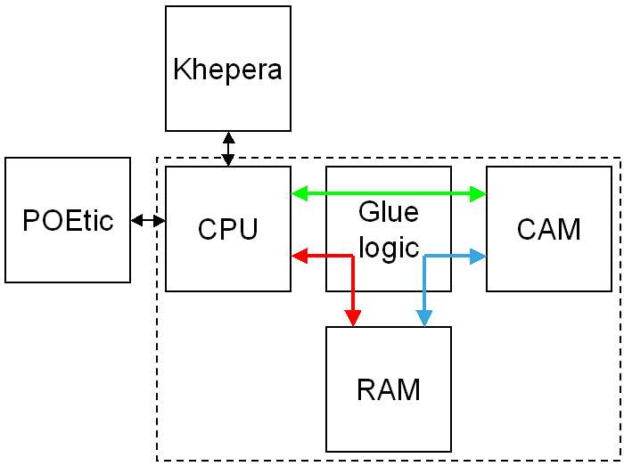 Architecture of the camera module
(inside the dashed block). The module is composed of a CPU, the camera
and a RAM which serves as a frame buffer. Glue logic implemented in a
CPLD is used to grab the pixels coming from the camera and store them
in the RAM. The RAM is mapped in the address space of the CPU,
therefore the CPU can access transparently the whole grabbed image. The
CPU interfaces with the Khepera robot (e.g. to send motor commands or
read sensors) and with the POEtic chip (a custom ASIC) or a desktop
computer (e.g. to send images and receive robot commands) over two
serial lines.
Architecture of the camera module
(inside the dashed block). The module is composed of a CPU, the camera
and a RAM which serves as a frame buffer. Glue logic implemented in a
CPLD is used to grab the pixels coming from the camera and store them
in the RAM. The RAM is mapped in the address space of the CPU,
therefore the CPU can access transparently the whole grabbed image. The
CPU interfaces with the Khepera robot (e.g. to send motor commands or
read sensors) and with the POEtic chip (a custom ASIC) or a desktop
computer (e.g. to send images and receive robot commands) over two
serial lines.
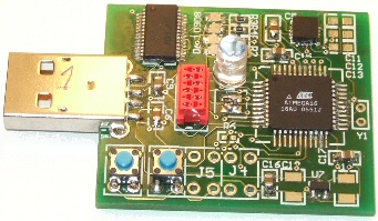
The camera module contains a 16 MHz 8-bit RISC CPU (Atmel ATmega64L),
the camera itself (OV5017), a 512KB SRAM, and a CPLD (Altera EPM7256)
which is used to implement interfacing logic. The high-level
architecture of the camera is illustrated in the figure.
Software
The task of the operating system (OS) of the camera is to transmit over
the serial line the camera images and the sensory information of the
Khepera. At the same time it listens for commands received over the
serial line.
Commands received over the serial line can be motor orders for the
Khepera robot, or changes of parameters of the module (e.g. size and
position of the frame to transfer). Commands consist of packets of 5
bytes where the first byte indicates the operation (e.g. motor command)
and the following bytes are command-dependent parameters (e.g. motor
speeds).
The operating system continuously reads the sensors of the Khepera
robot in background (proximity and floor sensors, wheel speeds), and
mirrors their state in local variables. Each time a new frame is
acquired, the operating system streams a data frame containing the
desired part of the image and the mirrored state of the Khepera sensors
on the serial line.
Several image transmission modes are implemented:
- Raw mode Images are
acquired and streamed without pre-processing: for each pixel a byte is
transferred.
- Raw filtered This mode
differs from the raw mode in that subsampled images are filtered along
the horizontal axis before being transferred to reduce image noise.
Filtering is done by sending the average of n pixels, where
ncorresponds to the horizontal subsampling factor.
- Temporal DPCM When there
are relatively small changes from image to image, it is worth sending
the difference between the current and the previous image with a more
coarse quantization. Here this difference is encoded in 4 bits,
therefore reducing the frame size by a factor two. This mode is however
only suited for quasi-static images, or when objects moveslowly, as no
adaptive quantization is yet implemented.
- JPEG-LS The speed of the
serial line limits the maximum frame rate. The size of images may be
reduced by compression, at the expense of higher CPU usage on the
camera module. Performing image compression on a 16 MHz 8-bit
microcontroller requires a low complexity compression algorithm. The
JPEG-LS low-complexity coder for still images with lossless and
near-lossless compression is used to compress the images with an
adjustable error level before streaming the video frame over the serial
line. The maximum pixel error is set by sending a corresponding command
to the camera module. In practice compression is beneficial for large
images, where the bottleneck is the transmission speed. For smaller
images the bottleneck is the processing time and in this case it is
more advantageous to stream the images without compression.


Images
provided by the camera module in 384x288 with different compression
ratios. Left: uncompressed image. Right: JPEG-LS with a maximum pixel
error of 15.